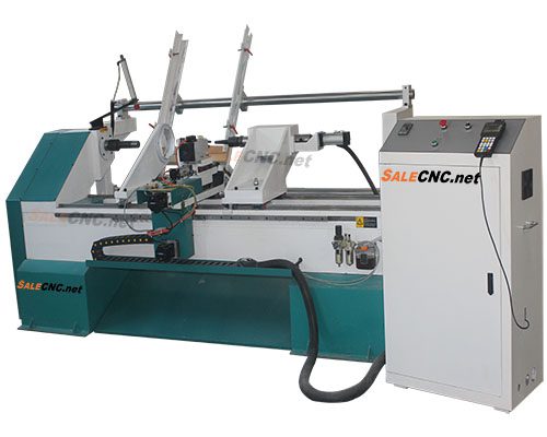
Several parts cut by CNC Lathe turning machine for wood working. The video presents several art work for furniture such as stair rail, table legs and so.
ตู้คอนโทรลเลอร์ Using the controller that can directly import DXF file from AutoCAD. It’s the most simple way to make wood from this CNC Lathe turning machine.
ภายในตู้คอนโทรลเลอร์
เซอร์โวมอเตอร์
ตัวอย่างการทำงาน
วีดิโอสอนการใช้งาน
1. เครื่องกลึงไม้ CNC แนะนำเครื่อง
2. เครื่องกลึงไม้ CNC แผงควบคุมต่าง
3. เครื่องกลึงไม้ CNC กลับ Home & การเซ็ต Origin Set Zero
Operation steps of single axis double cutter turning and milling integrated automatic feeding lathe
Steps of handle cutting
After power on, manually run each single axis movement to determine the movement direction. If the movement direction is opposite to the defined direction, it can be changed
Modify the phase sequence (a +, a – / B +, B -) of step motor.
According to the position of the defined origin coordinate of the machine tool, enter the menu – machine parameter configuration – zero return setting – zero return direction
Set the zero return direction.
Press the “diagnostic DGN” key – Manual level definition (the above row is the input level definition) to check whether the zero return switch is positive
Normal (manual trigger, port change).
After all the above are confirmed to be normal, it can be confirmed that the machine tool is connected normally
Machining settings
Processing speed: the processing speed when the lathe processes documents. The default value of the system is 500mm / min.
Idling speed: the moving speed of the processing program when it executes idling. The default value of the system is 1000mm / min.
Layered setting: the workpiece can be turned several times. The default is 1 time. The customer can modify it according to the thickness of wood.
Tool setting
Set parking space: press X+ or – to make the tool go to the unimpeded position where the workpiece stops after processing, and click the parking space button.
Open the diagnostic key for wood feeding, find the analog output, click key 6 to open, and then click key 8 to fix the wood after automatic feeding, close key 6 to exit the feeding support.
Tool setting: click the + and – buttons of X and y to make the tool move to the proper position of wood processing. The tool head is close to the four edges of the square wood or the surface of the round wood. Click the reset button.
Click OK to return the tool to the workpiece origin.
Loading file: select the drawing to be processed in the internal file of the U disk or handle (the file of the car needs to be saved at the beginning of D when drawing), and click OK.
Click the run key to start machining the workpiece.
Screw setting:
Switch to slot mode (click the mode switch button)
Click the menu buttons, select the user parameter list, find the screw machining list, and set the slot pulling speed: blank line 3000 machining 2000
Click Cancel to return to the previous menu, and set the number and angle of pull grooves. 0 degree is straight groove, and the number of pull grooves is the number of layers needed. Click Cancel to return to the main interface.
Start loading file: click the drawing prepared for processing in the USB flash disk or internal file. When drawing, the drawing slot file needs to save the beginning of S.
Tool setting: attach the slotting tool to the position where the wood surface is ready to be processed, and then clear it.
Click the run key to start the grooving process.
Screw processing speed
Spiral speed: the processing speed of pulling a twist rotating shaft to the next twist continuously.
Idling speed: the idling speed between twist and twist.
Screw process:
Number of spirals: the number of twist number to be processed.
Screw angle: the selected rotation angle of a twist during processing (default is 0, i.e. straight line).
Screw times: the same twist is processed several times (evenly distributed in depth each time).
One way screw: each time the processing of twist is started from the same side (to avoid lead screw clearance).
Milling and cutting cycle setting
Switch the mode to “milling and cutting”, click the panel diagnosis mode, find the analog output, turn off key 8, and exit the wood.
Turn on the black knob on the control cabinet.
Open the menu key, click the user parameter, find the list of pull cycle, select the file to be pulled (beginning with D), open the list of pull cycle, select the file to be pulled (beginning with s), click the cancel key to exit the list of pull cycle, and the workpiece will be processed by itself.
Safe height
Safety height: set the tool lifting height value of axis X, Y, Z,A and a during the processing, and the system default value is 40.000mm for axis Z
Axis. Other axis do not need safety height, and can be set to 0.
Tool lowering setting
Type of falling knife:
① Z movement only (only works when Z axis moves alone)
② Z movement (start as long as Z axis movement Function)
③ Unlimited speed (falling knife speed limit does not work).
Type of tool lowering::
① Only Z motion (only when Z axis moves independently)
② Z motion (only when Z axis moves)(3) no speed limit (speed limit of knife dropping does not work).
Knife height: The system defaults to 5.000 mm. After the Z axis is lowered to the knife height, the knife fall override will take effect.
Height of tool lowering:The system defaults to 5.000mm. When the z-axis is lowered to the height of the tool drop, the tool drop ratio starts to work.
Falling speed: the maximum speed of the Z axis when falling, the unit is mm / minute
Speed of tool lowering:Maximum speed of z-axis tool drop, unit: mm / min
Limit of tool lowering: ① All speed limit (as long as there is z-axis tool dropping in the process of machining, the limit will work), ② the first tool (machining
In the process, it only limits the first knife to fall).
Stop cutting setting
After the program processing, the coordinate axis cutting position. Including: lift Z axis, return to workpiece origin, return to machine origin


รีวิว
ยังไม่มีบทวิจารณ์