














 Back to P23-Fanuc Parts
Description
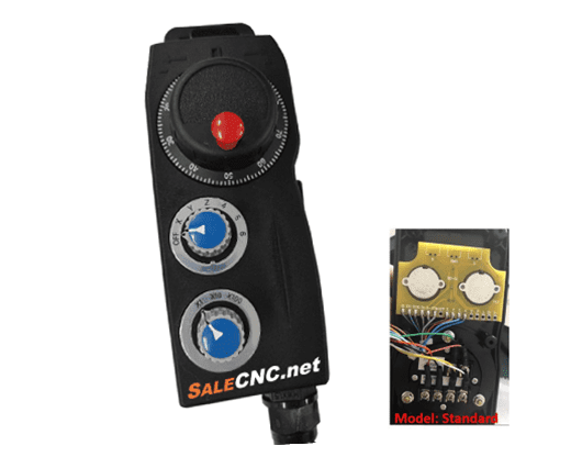
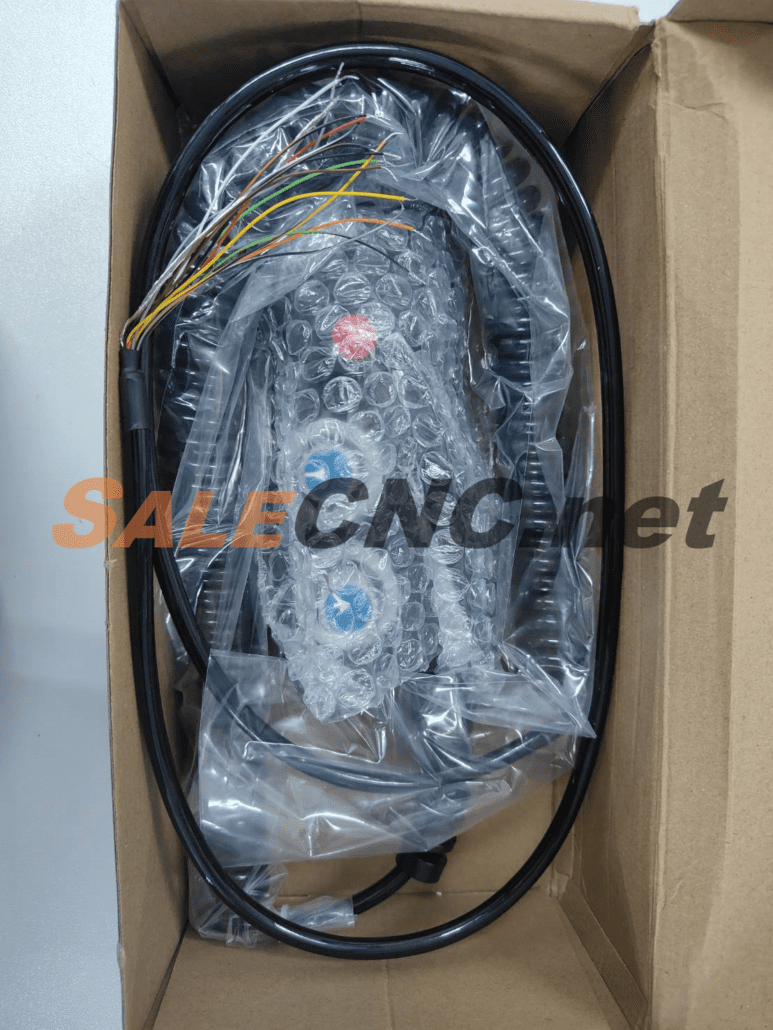
MPG Handheld Pulse Generator for Fanuc Systems



Integrated Wiring Diagram for MPG Handheld Mitsubishi 12 VDC
Important! If wiring is not performed correctly, bare copper ends must be isolated to prevent short circuits.

- Pulse Generator:
- Red – VCC (Pulse positive voltage)
- Black – OV (Pulse negative voltage)
- Green – A (Phase A output)
- White – B (Phase B output)
- Purple – A′ (Phase A complement)
- Purple and Black – B′ (Phase B complement)
- Shaft Selector Switch:
- Yellow – X (Axis selection X)
- Yellow and Black – Y (Axis selection Y)
- Brown – Z (Axis selection Z)
- Brown and Black – 4 (Axis option 4)
- Shaft Selector Switch (Continued):
- Pink – 5 (Axis option 5)
- Pink and Black – 6 (Axis option 6)
- Multiplier Switch:
- Gray – X1 (Multiplier selection X1)
- Gray and Black – X10 (Multiplier selection X10)
- Orange – X100 (Multiplier selection X100)
- Emergency Stop Switch (STOP):
- Blue – C (Contact C for stop function)
- Blue and Black – NC (Normally Closed contact for stop function)
- Working Light (LED Indicator):
- Green and Black – LED+ (Positive indicator voltage supply)
- White and Black – LED- (Indicator negative voltage supply)
- Common Terminal:
- Orange and Black – COM (Common point for switch inputs)
Note: For safety, ensure that bare copper wires are individually insulated and do not touch other conductors or the housing to prevent short circuits.
- Carefully read this manual before wiring to prevent operational issues with the handwheel.
- Do not connect the encoder’s positive and negative lines incorrectly, as high voltage can cause damage. The typical operating voltage is 5V, but specific systems like Mitsubishi (12VDC) or PLC (24VDC) require voltage verification.
- The COM terminal is the common point for the handwheel switches. Ensure it is properly connected for switch functionality.
- Handle the handwheel with care to avoid damage from impacts. Excessive force on dials and switches can affect their lifespan.
- When A- and B- signals are not available, DC 5-24V can be supplied to the handwheel indicator.
- Refer to specific system documentation for A- and B- signal configurations for Mitsubishi and PLC systems.
Handwheel Synthesis Diagram

Instructions: Connect the pulse generator’s red wire to the appropriate voltage source identified during procurement.
- Example: Connect to 12V for Mitsubishi systems.
- Example: Connect to 24V for PLC systems.
- Note: This applies when A- and B- signals are not utilized.
082-972-9329 (จิมมี่)
083-256-5981 (โกมินทร์)
E-mail : [email protected]

 salecnc.net
 salecnc.net
 salecnc.net


