










 Back to Electric Control / Switch
Description
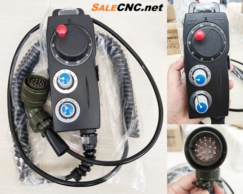
MPG Handheld Mitsubishi 12 VDC

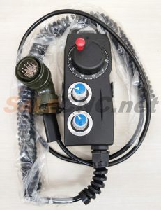
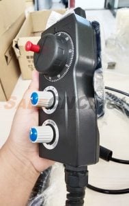
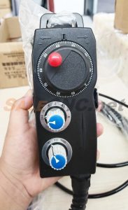
CNC MPG Handheld Box, Mitsubishi Compatible
- Selector switch for Axis selection: X, Y, Z, 4, 5, 6
- Selector switch for Feed rate multiplier: X1, X10, X100
Connector Interface

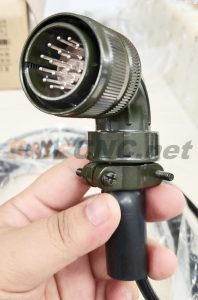
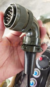
Machine Dimensions: MPG Handheld Mitsubishi 12 VDC
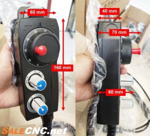
60 mm (W) x 160 mm (L) x 40 mm (H)
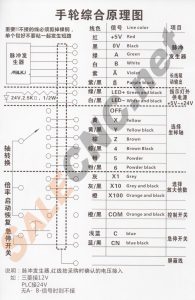
Integrated Wiring Diagram for MPG Handheld Mitsubishi 12 VDC
Important Note: Ensure proper wiring termination. If shielding is required, cut and individually insulate bare copper. Prevent short-circuiting.
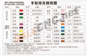
- Pulse Generator:
- Red – VCC (Pulse positive voltage)
- Black – OV (Pulse negative voltage)
- Green – A (Phase A)
- White – B (Phase B)
- Purple – A’ (Phase A complement)
- Purple and Black – B’ (Phase B complement)
- Axis Selector Switch:
- Yellow – X (Axis selection X)
- Yellow and Black – Y (Axis selection Y)
- Brown – Z (Axis selection Z)
- Brown and Black – 4 (Axis Option 4)
- Axis Selector Switch (Continued):
- Pink – 5 (Axis Option 5)
- Pink and Black – 6 (Axis Option 6)
- Feed Rate Multiplier Switch:
- Gray – X1 (Multiplier X1)
- Gray and Black – X10 (Multiplier X10)
- Orange – X100 (Multiplier X100)
- Emergency Stop Switch (STOP):
- Blue – C (Common contact)
- Blue and Black – NC (Normally Closed contact)
- Working Light (LED Indicator):
- Green and Black – LED+ (Positive indicator voltage)
- White and Black – LED- (Indicator negative voltage)
- Common Terminal:
- Orange and Black – COM (Switch input common point)
Note: Ensure all connections are properly insulated to prevent short circuits. Do not allow exposed copper to contact other components or the housing.
- Review this manual thoroughly before wiring to prevent operational issues with the handwheel.
- Connect the encoder’s positive and negative lines appropriately. Incorrect voltage can cause damage. Standard operation is typically 5V, but confirm voltage requirements for specific systems like Mitsubishi (12V) or PLC (24V).
- The COM terminal is the common point for the handwheel switches. Ensure this connection is made for proper switch functionality.
- Handle the handwheel with care. Avoid impact and excessive force on the dials and switches to maintain longevity and prevent damage.
- When A- and B- signals are not utilized, a DC 5-24V supply can be connected to the handwheel indicator.
- Compatibility Note: The availability of A- and B- signals may vary between systems (e.g., Mitsubishi, PLC).
Handwheel Assembly Diagram
Instructions: Connect the pulse generator’s red line to the recognized power source. For example:
- Mitsubishi systems typically require 12V.
- PLC systems may require 24V.
- This connection is not required when A-B signals are not used.