









 Back to Master Control & Automation Infrastructure
Description
CNC Controller RichAuto-A1X-10 System
RichAuto-AutoNow-A15S
Digital Signal Processing Control System
Download User Manual RichAuto-A1X 👉 Click Here
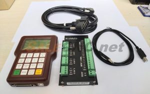
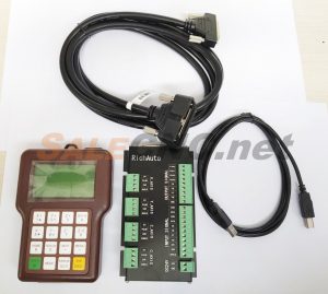
🟡 1 Set Includes:
- Control Remote
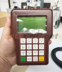
A15 Common Use Combination Keys
- ON/OFF + HIGH/LOW: Switch main shaft
- RUN + ON/OFF: Tool compensation
- MENU + ON/OFF: Auto tool preset
- RUN + (1-8): Break processing
- RUN + HIGH/LOW: Advanced process
- RUN + 9: Repeat last processing
- MENU + OK: System update
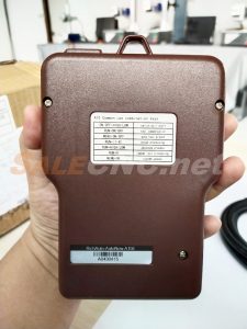
RichAuto-AutoNow-A15E A1X-10
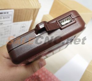
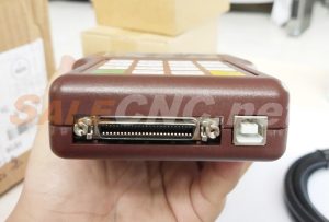
- Controller Board
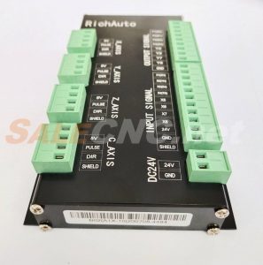
RichAuto-A1X-10 System
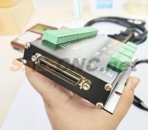
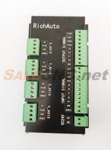
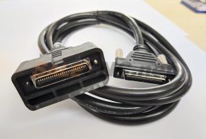
- 1×50 Core Cable
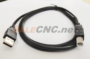
- USB Cable
🟡 System Characteristics
– High-Performance Core Processor: Based on an 8-core processing CPU with features of faster running speed and stronger processing capacity.
– Simple Handheld Key Operation: Features a 16-button operational mode and a comfortable handheld terminal, which are easy to learn and use, simple and quick to operate.
– Multiple Transports, Very Large Memory: Total off-line operation, multiple removable storage modes; 512MB internal memory, support for high-volume removable storage devices.
– Intelligent Pre-Reading Function: The Auto-Now system incorporates enhanced intelligence in pre-reading processing files. For new documents, pre-reading is only required the first time it is processed; the check can be skipped during the pre-read procedure if necessary to save time.
– Intelligent Memory Function: Backs up data in case of power failure.
– Parameter Storage and Restoration Function: Supports parameter backup and restoration. Parameters and files are stored separately to effectively prevent the loss of critical parameters.
– Two Machining Modes for Choice: High-precision mode guarantees the quality and precision of the workpiece; High-speed mode ensures working efficiency and saves time.
– Pre-Start Safety Check and Alarm Measures: Newly implemented safety warnings and hints for system exceptions.
– Better Encryption Capability: Hardware encryption, parameter settings encryption, running time encryption, and important internal processing file encryption prevent the system from being modified, deleted, or copied, thus safeguarding customers’ technology information and property.
– Better Performance on Anti-Interference: Performance on anti-interference has been verified through several CE tests and has significantly improved.
– Bigger Exploitability: The Auto-Now system basic edition supports an 8-in and 8-out user-defined I/O terminal function; users can entirely edit or define terminals as needed. Based on the 8-core processing CPU, secondary development is feasible. We can add special functions and applications to the system based on customer requests to meet the demands of different industries. This system features short cycle times, low costs, and high security.
🟡 Basic Operations of A1X Series
1. When the controller is powered on for the first time, press “Cancel” to enter the main interface. Then, press “Menu” to access parameter settings by selecting “Machine Setup.” Key modifications include “Pulse Equivalent” and “Table Size” (refer to the simple instructions for the calculation method of pulse equivalent; the set table size value should be less than or equal to the actual value).
2. Return to the main interface and verify that the positive and negative directions of each axis operate correctly. (If directions are reversed, adjust the motor coil for stepper motors or the parameter settings of the servo driver for servo motors).
3. Confirm the pulse equivalent value. If the positive and negative directions of each axis are correct, power cycle the system and return to zero. The home direction may be reversed; this can be modified by selecting “Machine Setup” and then “Home Setup,” which includes home speed, home order, and home direction.
4. The state of the eight input terminals is controlled by “Input Configuration.” The last four terminals are normally closed; they can be opened if needed, otherwise, do not modify them.
5. Modify working speed, speed scale, and processing attributes as required in “Auto Processing Setup.”
6. In “Operate File,” files can be copied from a U disk to the controller’s internal storage using “Copy File” for processing or upgrading, and deleted from the controller’s internal storage using “Delete File” to save space for new files.
7. Process File:
(1) Process U disk file: Read and process files directly from a U disk.
(2) Process internal file: Read and process internal copied files more steadily with better anti-interference performance.
🟡 Computing Method of Pulse Equivalent
Linear Axis: The pulse number sent by the control system when the machine moves per millimeter, unit: pulse/mm.
Revolving Axis: The pulse number sent by the control system when the machine revolves per degree, unit: pulse/degree.
🟡 Simple Troubleshooting Methods
1. System Cannot Be Initiated
1) When the controller is powered on, if “Rich Auto system is loading…” is displayed on the screen for an extended period and the system cannot initiate. Press and hold “OK” first, then power on simultaneously. “Rich Auto system is loading…” will appear on the screen. Release “OK” after 2 to 3 seconds; the controller will enter the emergency recovery interface.
Emergency Recovery State:
Upgrade System
View Version and Function
Format Internal
Initialize Parameters
Select “View Version and Function” to obtain the corresponding upgrade package from the manufacturer and upgrade the program to resolve the issue.
2) If “Assertion error” is displayed on the screen, handle it using the same method as described above, and perform “Format Internal” and “Initialize Parameters” at the end.
3) If the system loads to 100% and the screen is blank, perform the emergency recovery method as outlined in condition 1).
2. Blank Screen (No Text Displayed)
1) A blank controller screen upon powering on indicates that the programs have been lost, and emergency recovery operations are ineffective. In this scenario, the controller must be returned to the manufacturer for program recovery via refreshing.
2) If the system fails while running to *%, please return it to the manufacturer for repair.
3. Black Screen (No Light Shown on Screen)
1) If the controller screen is black with no text displayed, connect it to a computer for power supply using the square USB port. If the controller displays normally, there is likely an issue with the external power supply connected to the machine. If not, contact the manufacturer and return the controller to the factory for repair.
2) A black screen may result from a short circuit caused by misconnected 24V supply or other high-voltage power supplies, leading to breakdowns in the controller or interface board. Return to the factory for repair.
4. Cannot Read U Disk or Process Files on U Disk
1) Check if the controller’s USB flat port is damaged when a U disk cannot be read. Format the U disk and change the format to FAT32 if the port is intact, refresh the program, and then test reading the U disk again. If the port is damaged, do not attempt to repair or disassemble the product yourself; contact the manufacturer for service.
2) Press and hold any two buttons simultaneously and then power on. The controller will enter “U Disk Mode.” In this mode, it will be recognized as a hardware device on the computer and can be used as a U disk for file copying, with a storage capacity of 512MB.
5. Axis Values Cannot Be Cleared
1) If axis values cannot be cleared, first check the controller as follows: Verify if the controller is in mechanical coordinate mode under manual mode. If the screen displays:
AX 0.000 manual
AY 0.000 F1
AZ 0.000 low speed
Then the system is in mechanical coordinate mode. Press “Menu” and any numerical button from 1 to 9 simultaneously to switch to working coordinate mode to clear values.
2) If the above is not the case, check if all 16 buttons are functional via “Buttons Check” in “System Setup.” If not, return the unit to the factory for repair.
🟡 Precautions for Use:
1. Never use the products in environments with strong interference or high-intensity magnetic fields. Working temperature: 0-70°C, working humidity: 0-90% (non-condensing).
2. Ensure the U disk is inserted in the correct direction. Do not hot-plug the signal transmission cable connecting the controller and the machine tool.
3. Do not remove the U disk while processing files from it to prevent data transmission interruption.
4. Exercise strict caution to prevent conductive materials (e.g., metal particles, dust) or corrosive liquids from entering the controller.
5. Connect the machine tool chassis to the ground for safety and interference prevention.
6. Unauthorized disassembly is strictly prohibited; no component within the controller is user-serviceable.
7. When the controller is not in use for an extended period, power it down and store it properly.
8. Protect the controller from water, dust, and fire during operation.
9. Do not use conductive chemical solvents to clean the controller.
10. The lifespan of the main spindle motor bearing is inversely proportional to its rotational speed.
🟡 Important Statements:
We are not responsible for any losses incurred due to operational errors or non-compliance with operating instructions. BEIJING RichAuto S&T Co., Ltd. reserves the right of final explanation and revision for all information, data, technical details, and other content within this manual.
🟡 Basic Usage Examples
Controller Usage SQNC-0501HDDC-L07-100088 Board 257-B050S-AM42 (1) – How to Connect the Controller
Controller Usage SQNC-0501HDDC-L07-100088 Board 257-B050S-AM42 (2) – Introduction to Controller Buttons
Controller Usage SQNC-0501HDDC-L07-100088 Board 257-B050S-AM42 (3): Controller Usage with Servo Stepping Motor & Drive
Controller Usage SQNC-0501HDDC-L07-100088 Board 257-B050S-AM42 (4): Controller Usage with Spindle Water & Inverter