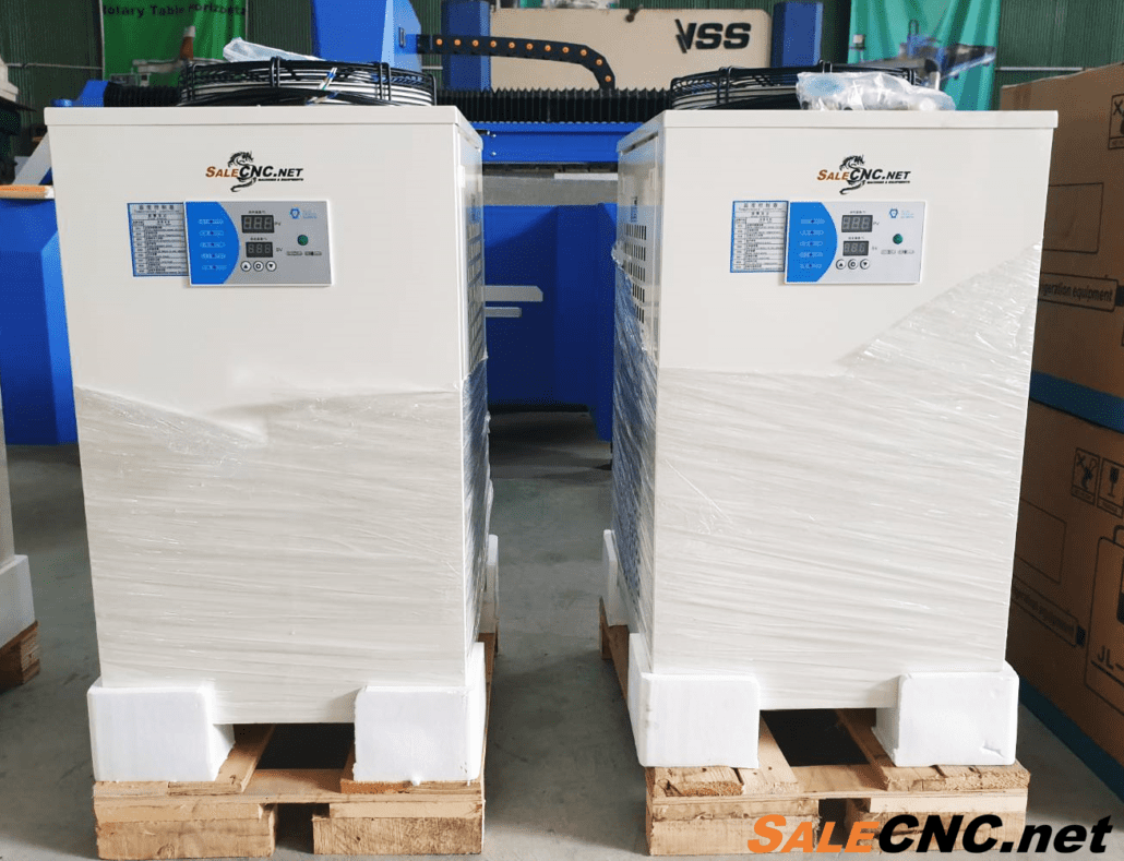
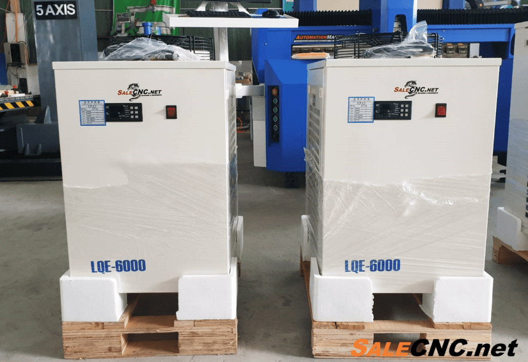
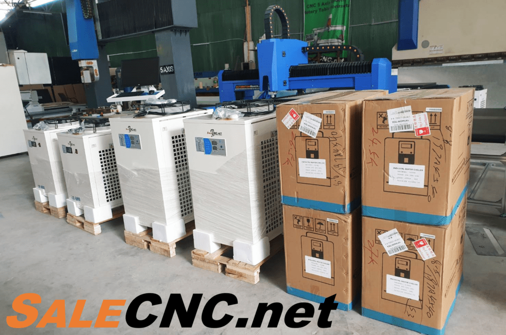
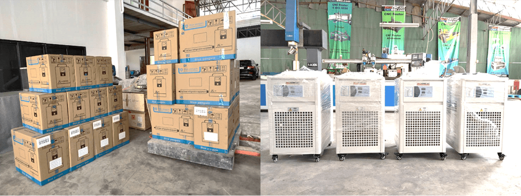
Precise Temperature Control Industrial Cooling System
Thailand is located in the tropical zone, experiencing high temperatures year-round. In industrial settings, elevated operating temperatures for machinery, electronic equipment, and other devices can lead to component failure, reduced operational efficiency, and in extreme cases, fire hazards due to heat accumulation. Similar to how elevated body temperature affects human health, excessive heat in machinery impairs performance. Therefore, proactive maintenance and effective thermal management solutions are crucial for ensuring equipment longevity and optimal performance. A Chiller system serves as an essential component in addressing high-temperature challenges in industrial machinery.
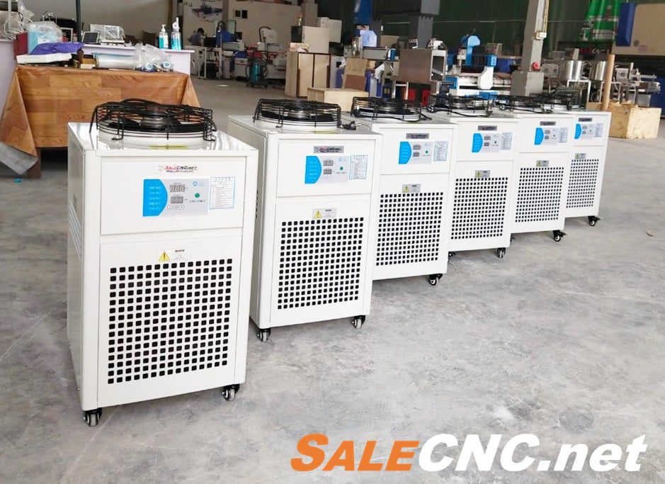
A Chiller is a refrigeration unit designed for cooling and temperature reduction. Available in various sizes, its primary function is to generate cooling capacity by transferring heat from the process fluid, typically water, to a refrigerant cycle. Chillers are widely implemented in industrial facilities to manage the operating temperatures of machinery, thereby extending equipment lifespan and maintaining peak operational efficiency.
Utilizes water as the primary medium for heat exchange and cooling.
Widely adopted in industrial environments to dissipate heat from machinery, ensuring sustained operation and optimal performance.
For example : Closed system pond, Hydraulic injection molding machine, CNC Engraving Cutting CO2, CNC Laser Engraving UV, CNC Router Milling, CNC Fiber Laser and other.
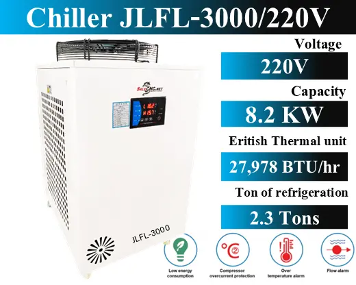
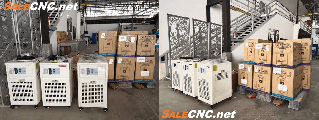
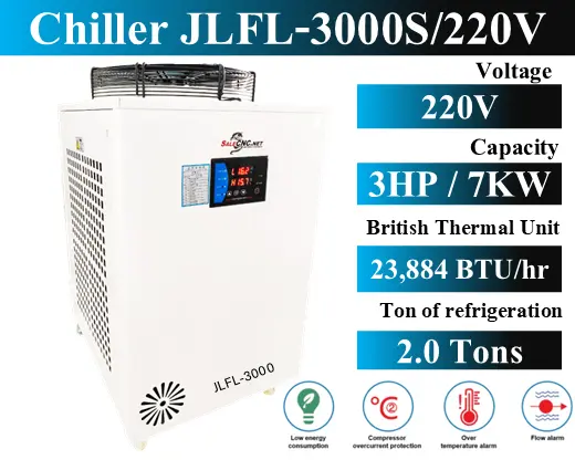
Chiller Unit for Sale – Model JLFL-3000 (220V)
220V
Designed for cooling CNC machines, fiber lasers, and similar equipment, ensuring stable operation by preventing overheating during intensive use.
FEATURES
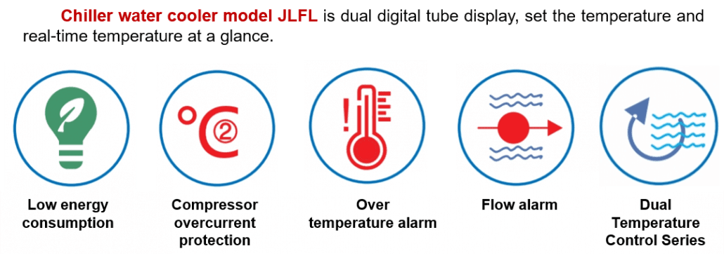
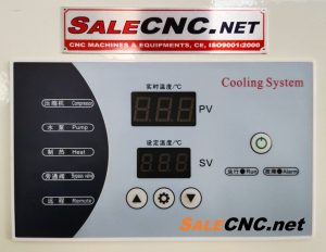
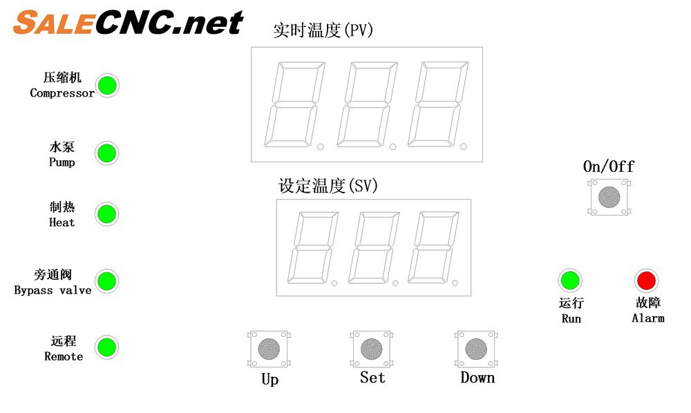
Dual digital display provides simultaneous readouts of set temperature and real-time temperature.
Full power refrigeration with micro-process temperature control capabilities.
Achieves high-precision temperature control, with fluctuations maintained within ±0.5℃.
Integrated functions include sensor fault self-diagnosis and water flow alarm.
Main board utilizes a highly integrated chip for enhanced anti-interference performance.
Machine Dimensions
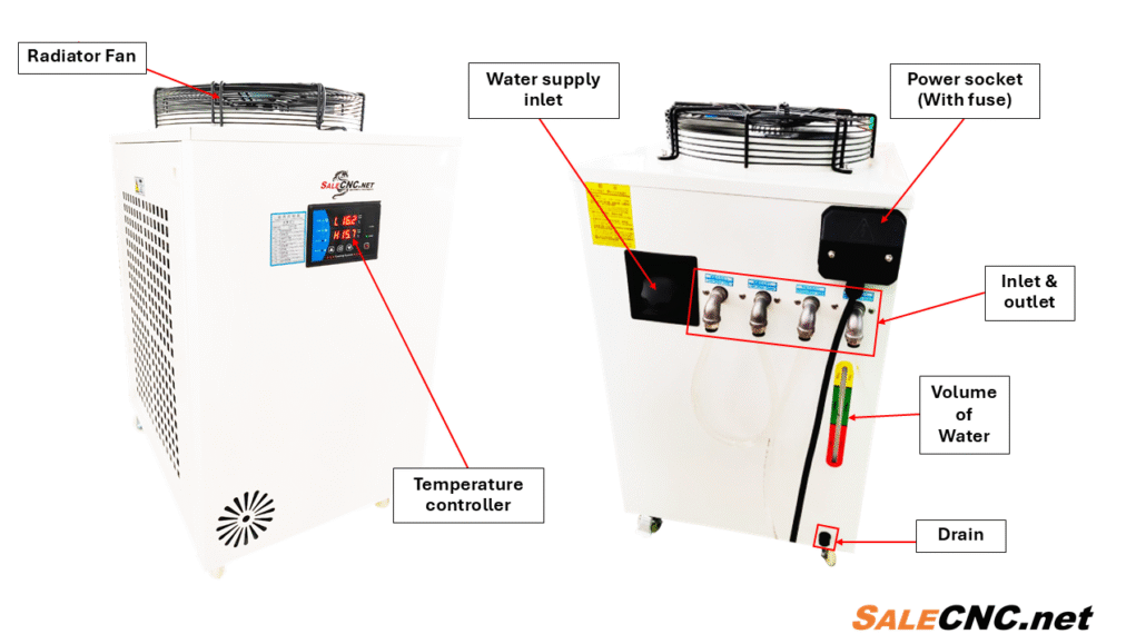
Alarm Indicator
Controller Interface
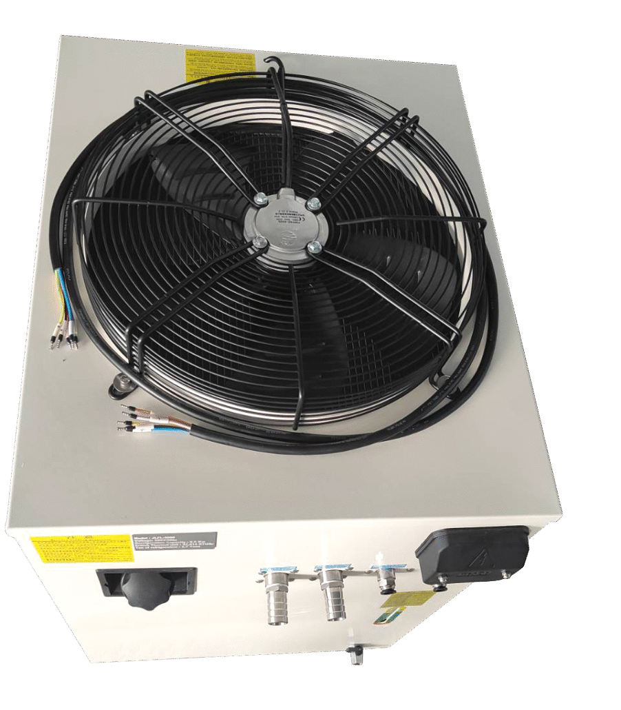
Top View
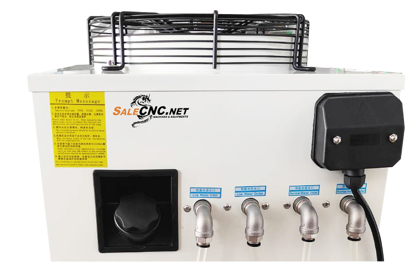
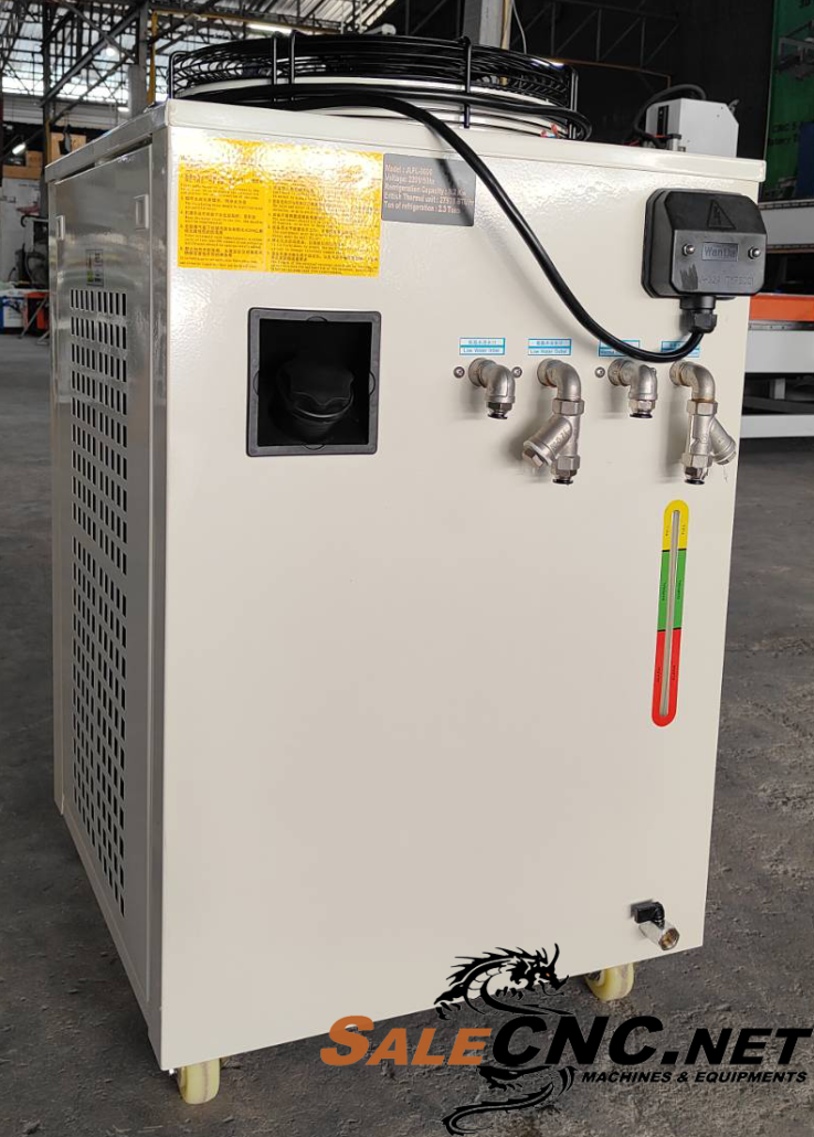
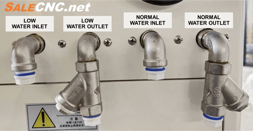
Inlet and Outlet Connections
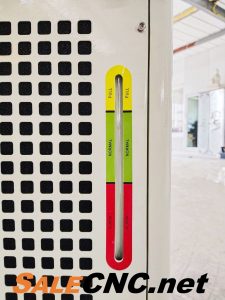
Internal Water Level Indicator
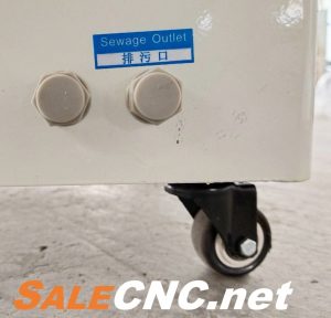
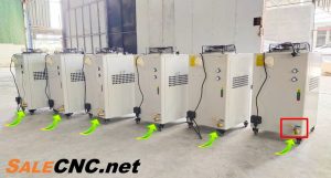
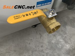
Drain Port
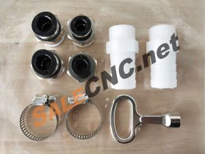
Included Accessories
Side View
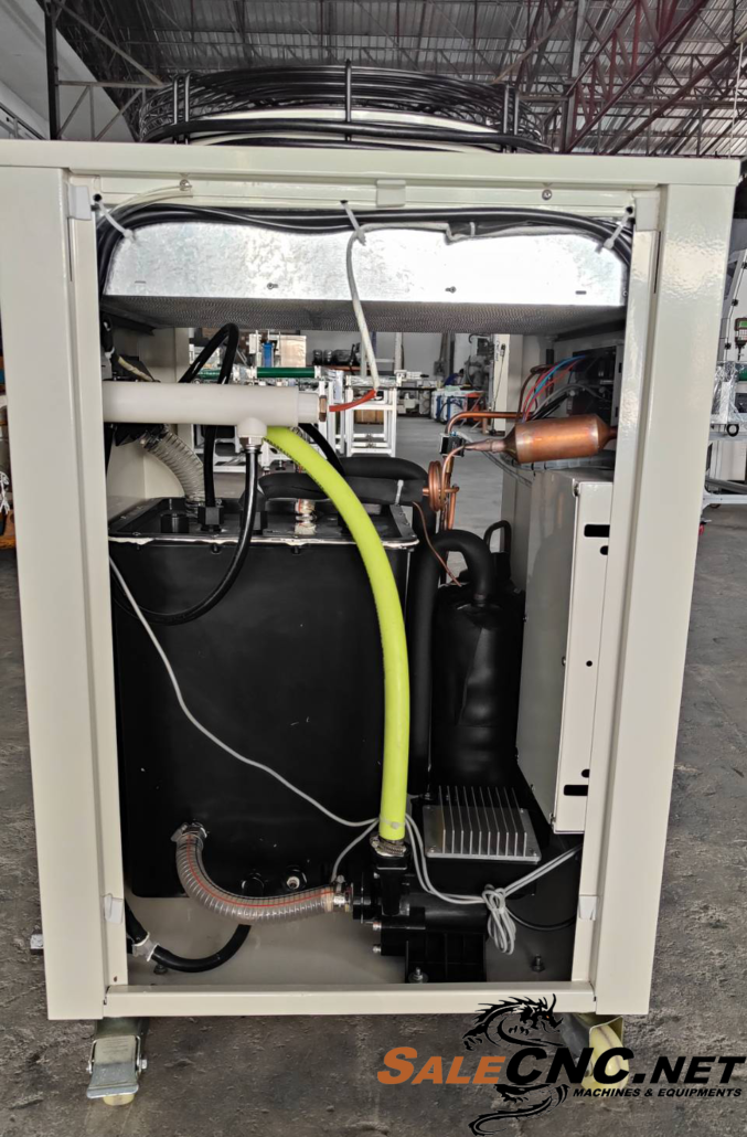
Rear View
Optional drain port available with internal diameters of 19 mm or 32 mm.
Drain Port (Internal Diameter 32 mm)
Machine Components
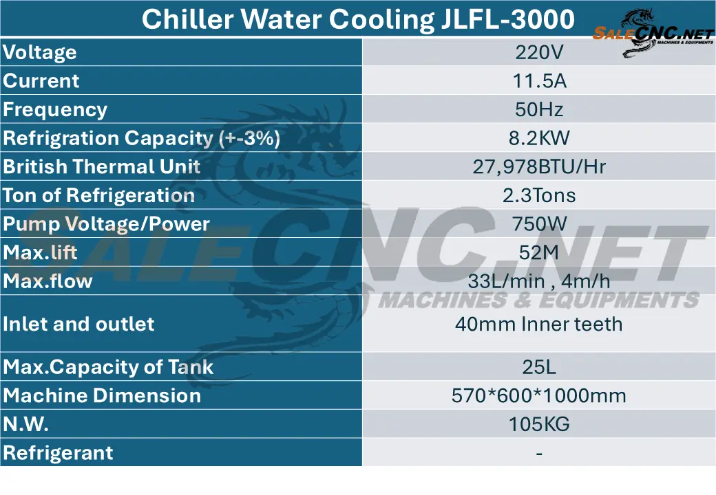
Technical Specifications
Inlet and Outlet Connections
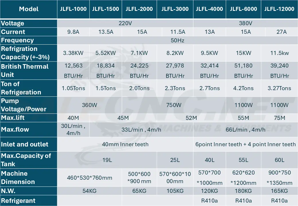
Chiller Model Comparison
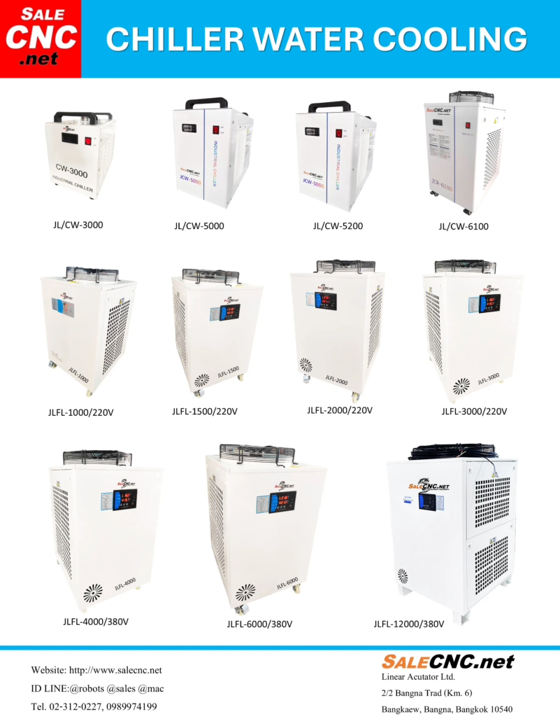
Chiller Water CoolingModel JLFL Series
Understanding BTU Measurement
BTU, or British Thermal Unit, is a standard unit of energy used to quantify the amount of heat required to raise the temperature of one pound of water by one degree Fahrenheit at constant pressure. It is commonly employed in the United States and other regions to specify heating and cooling capacities.
The process for measuring BTU involves the following steps:
System Definition: Identify the system for which the BTU measurement is pertinent, such as a heating system, cooling system, or appliance like a furnace or water heater.
2. Substance Identification: Specify the substance undergoing heat energy measurement. While often water, the substance can vary based on the application.
3. Temperature Change Measurement: Record the initial and final temperatures of the substance. For instance, when assessing BTUs generated from fuel combustion in a furnace, measure the water temperature before and after the heat exchange process.
4. Heat Energy Calculation: Utilize the following formula to compute heat energy in BTUs:
Heat energy (BTU) = mass (lb) × specific heat (BTU/lb°F) × temperature change (°F)
In this formula:
‘mass’ denotes the substance’s mass in pounds.
‘specific heat’ refers to the substance’s specific heat capacity in BTU per pound per degree Fahrenheit (BTU/lb°F).
‘temperature change’ represents the difference in temperature in degrees Fahrenheit.
5. Efficiency Consideration: In certain scenarios, the efficiency of the system or device may need to be factored in to determine the actual BTU output or input.
Collectively, BTU measurement offers a standardized method for quantifying thermal energy, crucial for applications spanning HVAC (heating, ventilation, and air conditioning), culinary processes, and industrial operations.
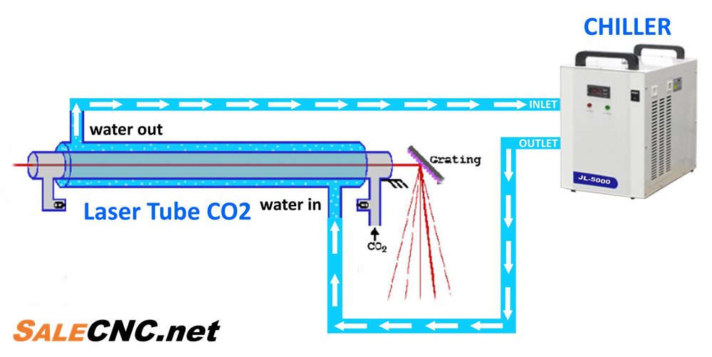
Operating Principle: CO2 Laser Tube and Chiller System
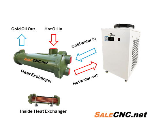
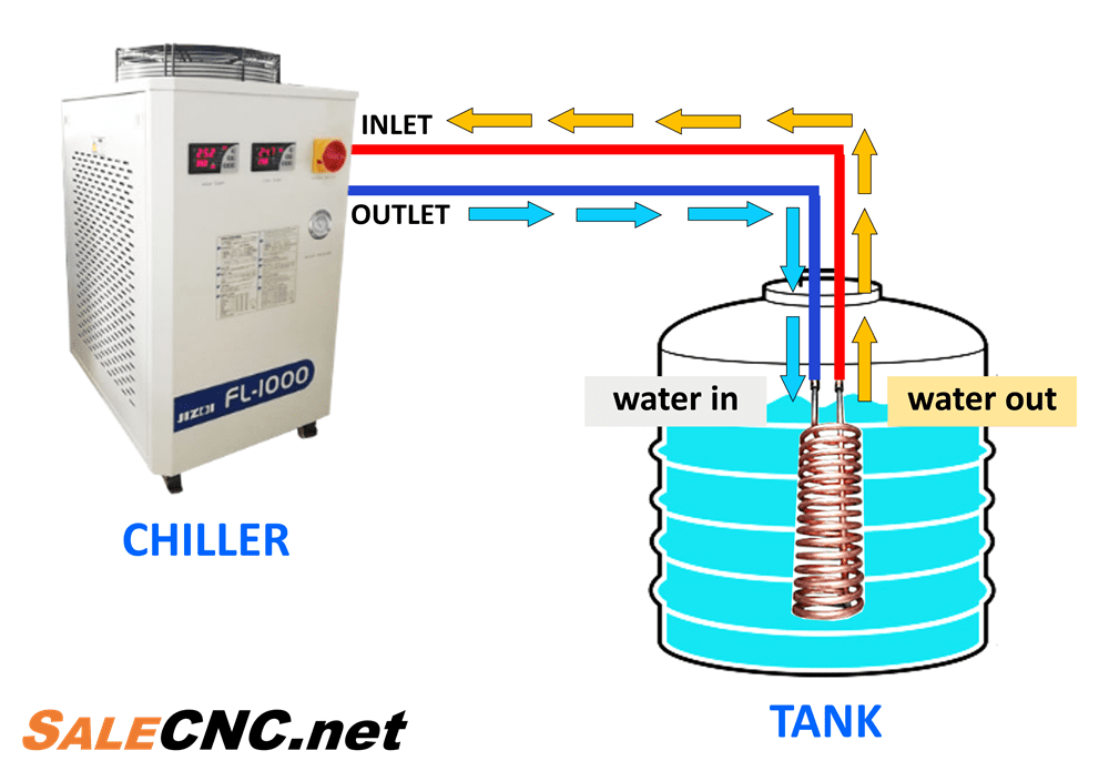
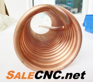
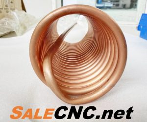
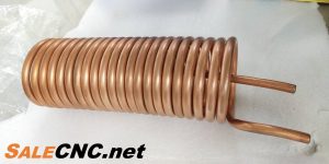
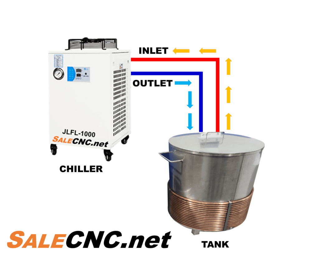
Optional Accessory: Heat Exchanger
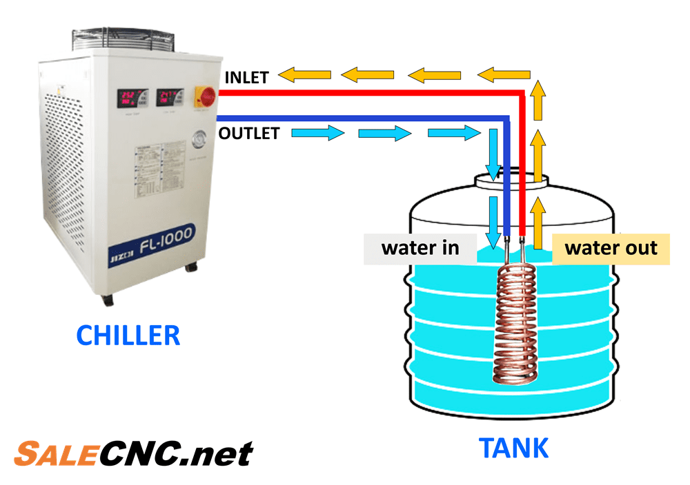
The Heat Exchanger connects to the chiller and is submerged in water to further reduce water temperature.
Price: 3,000 Baht
Heat Exchanger Installation with Chiller Unit
Heat Exchanger: An Auxiliary Device for Chillers to Further Reduce Water Temperature | SALECNC.net
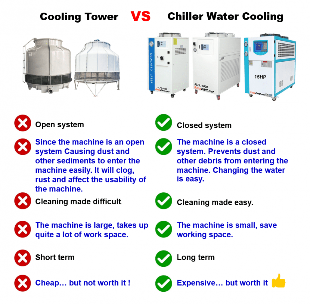
Chiller Water Coolingvs.Cooling Tower
Cooling Towers are primarily utilized in industries such as plastic injection molding. However, they present several drawbacks. Their large physical footprint, open-system operation, and susceptibility to dust and sediment ingress can compromise equipment performance and reduce operational lifespan. Consequently, industrial facilities increasingly favor Chiller Water Cooling systems, which offer a more compact footprint, space efficiency, and a closed-system design that effectively prevents contaminants. This leads to enhanced reliability and extended service life.
Industrial plants are increasingly adopting Chiller Water Cooling systems due to their compact size, space-saving design, and closed-system operation, which effectively prevents dust and sediment. These systems offer extended operational longevity.
Cooling Tower
Chiller Water Cooling
❌ Open system operation.
✅ Closed system operation.
❌ Prone to dust and sediment ingress, leading to potential clogging, corrosion, and compromised performance.
✅ Effective prevention of dust and sediment entry. Simplified water maintenance procedures.
❌ Complex and difficult maintenance procedures.
✅ Straightforward and easy maintenance.
❌ Large footprint requiring significant workspace.
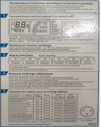
เมื่อเครื่องตรวจพบความผิดปิกติที่ช่อง PV จะแสดงอุณหภูมิ และรหัสข้อผิดพลาดสลับกันไปมา ในกรณีที่ตรวจพบข้อผิดพลาดหลายจุด สามารถกดปุ่ม Up หรือ Down เพื่อดู
Normal temperature water set temperature = [low temperature water set temperature] + [F01 normal temperature water temperature difference] , Not controlled by the upper and lower temperature limits
F01
Automatic working
1
0~1
0: not used / 1: used
F03
Low temperature water set temperature
23.0℃
【F06】~【F05
The function of the parameters is detailed in: 5 Control Logic.
F04
Control temperature difference
1.0℃
0.1~20.0℃
The function of the parameters is detailed in: 5 Control Logic.
F05
Temperature setting upper limit
30.0℃
【F06】~90 ℃
Low temperature water set the settable temperature range.
F06
Temperature setting lower limit
20.0℃
-38~【F05】℃
Low temperature water set the settable temperature range.
F07
Temperature over temperature upper limit
35℃
0~99℃
Alarm when the temperature of low temperature water or normal temperature water is greater than or equal to this value.
F08
Over temperature lower limit
4℃
-38~99℃
When low temperature water or normal temperature water temperature is less than or equal to this value, it will alarm.
F09
–
F10
Off the compressor temperature difference
3.0℃
0.3~15.0℃
–
F11
Heating temperature difference
2.0℃
0.1~20.0℃
When the electric heating is controlled (that is, the [function selection] is set to 2 or 3), this parameter is valid. / The function of the parameters is detailed in: 5 Control Logic.
F12
Low temperature water temperature compensation
0
-9.9~9.9℃
–
F13
Room temperature water temperature compensation
0
-9.9~9.9℃
Add
F14
Compressor anti-frequent start time
2 minutes
1~5 minutes
–
F15
Compressor start delay
30 seconds
0~255 seconds
Press the start button for at least the set time before allowing the compressor to start
F16
High/low temperature alarm delay
10 seconds
0~255 seconds
After the set time is delayed after the power is turned on, the detection of low temperature water and normal temperature water temperature is too high/low faults.
F17
Flow alarm delay
3 seconds
0~255 seconds
After pressing the power button, it will alarm after detecting the flow switch input for this time
F18
Level alarm delay
5 seconds
0~255 seconds
After power-on, it will alarm after detecting the input of the level switch for this time
F19
Pressure detection delay
10 seconds
0~255 seconds
After turning on the compressor and delaying the set time, start to detect pressure failure.
F20
DI4 input selection
0
0~1
0: Normal temperature flow / 1: Phase sequence switch
F21
Pressure Switch
0
0~2
0: Normally open / 1: Normally closed / 2: Disabled
(When set to normally open, the switch is closed and alarms)
F22
Room temperature flow/phase sequence
0
0~2
0: Normally open / 1: Normally closed / 2: Disabled
(When set to normally open, the switch is closed and alarms)
F23
Low temperature flow switch
0
0~2
When set to normally closed, the switch is disconnected and alarms
/ When set to disable, the state of the corresponding switch is not detected.
F24
Level Switch
0
0~2
When set to normally closed, the switch is disconnected and alarms
/ When set to disable, the state of the corresponding switch is not detected.
F25
Compressor overload switch
0
0~2
When set to normally closed, the switch is disconnected and alarms
/ When set to disable, the state of the corresponding switch is not detected.
F26
Alarm relay function
1
0~1
0: Alarm signal, control the relay output according to whether the unit has a fault
(**Relay NC point: disconnect when the unit fails, and close when the unit is in standby or normal operation; )
(**Relay NO point: pulls in when the unit fails, and disconnects when the unit is in standby or normal operation. )
/ 1: Normal operation signal, according to whether the unit is operating normally to control the relay output
(**Relay NC point: disconnect when the unit is operating correctly, and close when the unit is in standby or failure; )
(**Relay NO point: when the unit is operating correctly, it is closed, and when the unit is in standby or faulty, it is disconnected. )














 View All Products